
This is an old revision of the document!
Warning: Undefined array key 1 in /data/docs.osukl.com/public_html/lib/plugins/note/syntax.php on line 103
Warning: Undefined array key 1 in /data/docs.osukl.com/public_html/lib/plugins/note/syntax.php on line 103
Warning: Undefined array key 1 in /data/docs.osukl.com/public_html/lib/plugins/note/syntax.php on line 103
Warning: Undefined array key 1 in /data/docs.osukl.com/public_html/lib/plugins/note/syntax.php on line 103
Warning: Undefined array key 1 in /data/docs.osukl.com/public_html/lib/plugins/note/syntax.php on line 103
Warning: Undefined array key 1 in /data/docs.osukl.com/public_html/lib/plugins/note/syntax.php on line 103
Warning: Undefined array key 1 in /data/docs.osukl.com/public_html/lib/plugins/note/syntax.php on line 103
Warning: Undefined array key 1 in /data/docs.osukl.com/public_html/lib/plugins/note/syntax.php on line 103
Warning: Undefined array key 1 in /data/docs.osukl.com/public_html/lib/plugins/note/syntax.php on line 103
Warning: Undefined array key 1 in /data/docs.osukl.com/public_html/lib/plugins/note/syntax.php on line 103
Warning: Undefined array key 1 in /data/docs.osukl.com/public_html/lib/plugins/note/syntax.php on line 103
Warning: Undefined array key 1 in /data/docs.osukl.com/public_html/lib/plugins/note/syntax.php on line 103
Warning: Undefined array key 1 in /data/docs.osukl.com/public_html/lib/plugins/note/syntax.php on line 103
Warning: Undefined array key 1 in /data/docs.osukl.com/public_html/lib/plugins/note/syntax.php on line 103
Warning: Undefined array key 1 in /data/docs.osukl.com/public_html/lib/plugins/note/syntax.php on line 103
Warning: Undefined array key 1 in /data/docs.osukl.com/public_html/lib/plugins/note/syntax.php on line 103
Warning: Undefined array key 1 in /data/docs.osukl.com/public_html/lib/plugins/note/syntax.php on line 103
Warning: Undefined array key 1 in /data/docs.osukl.com/public_html/lib/plugins/note/syntax.php on line 103
Warning: Undefined array key 1 in /data/docs.osukl.com/public_html/lib/plugins/note/syntax.php on line 103
Warning: Undefined array key 1 in /data/docs.osukl.com/public_html/lib/plugins/note/syntax.php on line 103
Warning: Undefined array key 1 in /data/docs.osukl.com/public_html/lib/plugins/note/syntax.php on line 103
Warning: Undefined array key 1 in /data/docs.osukl.com/public_html/lib/plugins/note/syntax.php on line 103
Warning: Undefined array key 1 in /data/docs.osukl.com/public_html/lib/plugins/note/syntax.php on line 103
Warning: Undefined array key 1 in /data/docs.osukl.com/public_html/lib/plugins/note/syntax.php on line 103
Warning: Undefined array key 1 in /data/docs.osukl.com/public_html/lib/plugins/note/syntax.php on line 103
Table of Contents
4166 Build Instructions
Updating software on USB
Go to (S) Drive.
Select Binaries for Embedded.
Select 4166.
select offshore_159.
S:\Binaries for Embedded\4166
Copy file onto USB.
Take the USB out.
Disconnect all power from Screen.
Insert USB into (program update port)
Power up Screen.
Wait until company logo appears.
Power off and remove USB.
Power up and check software required is correct..
Before commencing build, program 10823 Dual Engine PCB and TX6Q module.
Programming Instructions 10823 Dual Engine PCB
Atmel Backlight/PSU driver Programming Instructions
Setting up the device for programming:
The 202325 Backlight/PSU driver can be flashed over the AVR’s ISP programming interface in the following steps:
1. Connect the programming device to a PC with AVR Studio
2. Connect the AVR Programmer to the ISP interface PL3 of the 202325 board.
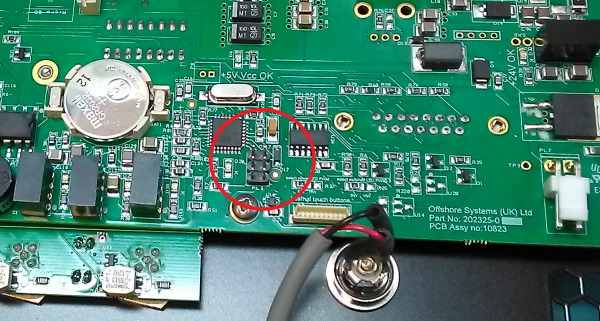
3. Power board up.
4. In AVR Studio select “Tools” → “Device Programming”, select the Tool you are using, press “Apply” and check the “Target Voltage” by pressing the “Read” button next to it. If the target voltage is less than 4.7 V, turn the ISP connector to opposite position.
5. Select the “Fuses” menu from the left panel and set up the following values (see the figure below):
a. BOOTLEVEL = 2V7 b. Spien = checked c. CKDIV8 = Uncheck d. Bootsz = 4096_7000 e. SUT_CKSEL = EXTXOSC_PLLIN_EXTXOSC_16KCK_14CK_64MS (last selection)
6. Then press the “Program” button
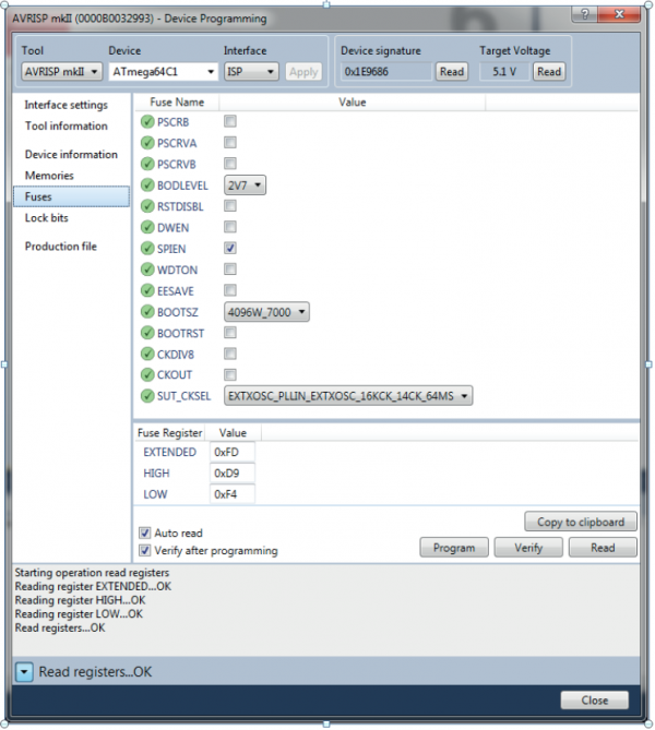
Programming the main program via ISP:
7. Select the main program by clicking on “Memories” menu on the left side.
Push “…” button next to the path of the “Flash (64KB)” file. Choose the hex file, where x is the latest released revision as per : “S:\Code\Production\4165 4166 Dual Engine Portrait Display\201578.hex”
8. Then press the “Program” button.
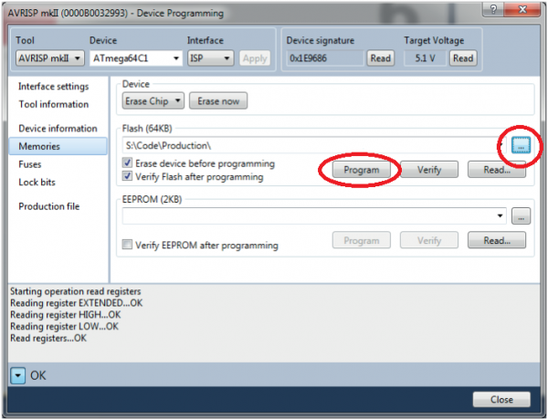
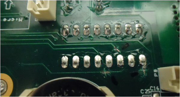
Programming Instructions TX6Q Module

The process of flashing the TX6Q board is a three step process. First we boot a boot loader called u-boot over the USB cable. Then we use the bootloader to copy a release file onto the NAND chip. Lastly we configure the chip the newly flashed bootoader. It is also recommended to wipe the chip before flashing to make sure no old software or configuration is left on the chip.
Requirements
- USB to Serial converter installed and working
- Board with OTG (Red one) 201226
- mini USB cable
- TX6Q chip
- 24V power supply
- Power cable for the board
- Mfg Tool
- Putty
Erasing the Chip
- Insert the TX6Q into the board.
- Do not swtich 24V power supply on until all connections are done.
- Make sure the board switch is off position.
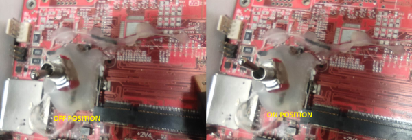
- Make sure the small jumper at PL1 is NOT across the two pins.
- Plug the mini USB cable into the board and PC.
- Plug the USB to Serial converter into the board and PC.
- Run MfgTool2.exe from S:\Code\Production\TX6Q Flashing Tool. (Do not click “Start”.)
- Switch the 24V power suplly on.
- Click “Start” MfgTool2 and switch power on the board approximately for a 2 seconds (using the RED/Silver Switch) until the see below picture and switch power off again by using the Red/Silver switch.
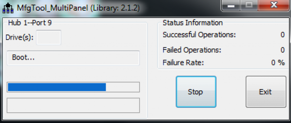
- Open Putty with Connection Type ‘Serial’, the correct COM port Port Selected (You can check the COM in ‘Device Manager’ under ‘Ports’) and a Speed of ‘115200’ and click “Open”.
- You should see some flowing codes in Putty screen.
- Switch Power on the board (using the Red/Silver Switch) again while hitting the Enter button Continuously on your keyboard. (At same time.)
- In putty you should have the following prompt:
TX6Q U-Boot >
TX6Q U-Boot >
- Type in the following command and hit Enter:
nand erase.chip
- This will completely wipe the entire TX6Q module. - You Will See:
OK >
TX6Q U-Boot >
- Switch off the module (toggle the Red/Silver switch)
Booting from USB and Flashing Software
Now let’s boot over the USB to our own bootloader which will allow us to copy the content from a USB stick onto the NAND flash memory.
- Make sure everything is connected up just like in the Erasing the Chip step.
- Place the jumper at PL1 to be across the two pins.
- Keep the miniUSB cable connected to the board's SK2 and the PC
- Insert USB stick which contains the correct release data e.g. oceanic_112 into ‘USB 3’
- Switch on the module (Toggle Red/Silver Switch).
- After the flash stops and the linux tries to boot, you will see “Starting kernel” in PuTTy… turn the board off (toggle Red/Silver Switch) and turn the power of by 24V power supply.
- Click “Stop” MfgTool and close Putty and MfgTool.
- Repeat *Erasing the Chip* steps without typing
nand erase.chip
- You Will See
TX6Q U-Boot >
- Type the following:
env default -a >
saveenv >
- Power off board
Programming Completed
Electronic Assembly
Add resistor 201880 to position R102 if not already fitted

QC CHECK
Ensure the external surfaces of the case are clean and not scratched – reject if they are damaged in any way.
The anodizing (or powder coating) is very fragile so take care at all stages of assembly – store on bubble wrap where possible. DSUB connector (Secure with screw locks) Heat sink assembly.
Place the heat sink bobbin 202353 into the large hole and hold it in place using the heat sink mounting plate 202366. Using four M3x8 screws 202429, attach the heat sink 202432.

Insert connector all the way into the board. position into casing and secure with all 6 screws as per SOP.


Once you have finished the soldering, inspect the joints to ensure correct flow has occured, Remove standoffs.


Top side

Fit Dual Engine PCB Align with pins on CAN PCB and DSUB connector. Fit screws and shake proof washers x 6 Fit coin cell battery Solder pins on DSUB to PCB


Then strip and tin the two ends.

Fit 4x holding screws M2 x 6 203186 (loosely) Flip upside down (carefully) so that the screws are at their maximum travel.

Cut two thin double sided strips and stick to the two longest edges.

Solder TFT wires to Dual Engine PCB.

Fit LVDS cable to TFT and J1 on Dual Engine PCB
Use Takpak on both ends to help hold the cable in place.

Fit rear case to bezel, and fit 2x screws M3x8 202429 just to hold it in place whilst on the soak bench. Fill out paperwork to stay with the unit for remainder of the process (QMF 20).
Check the screen when on soak bench for dead pixels and ensure all data is being read.
Do pull tests on wires to ensure they are held in place securely, check all fixings and that tak pak has been added where needed.
Seal up and add void sticker.
Test Procedure
Equipment used
- SOAK BENCH
- Small flat-bladed screwdriver for changing switch positions
- Test remote button set, connected to DUT
- Connect the built unit to the test bench, so that the J1939 Port (Brown tape), J1939 Stbd (Red tape) and NMEA (Blue tape) Wires are connected.
- Connect the power supply cable to the unit
- Unit should power on and the data displayed should reflect the status on the Test Bench Screen
- Check for information showing on gauges that it shouldn't. For example if “Port” is shown on the Soak Screen, then only the port gauges should be active. There is a brief period until data clears when the soak bench changes data line which is normal.
- Now check the brightness controls work with the test button set
- Now check the rotary switch changes engine type (Check with user manual)
- Now Check DIP switches change screen configuration (Check with user manual)
- Now Check the alarms work by pressing the “Alarms” button on the soak bench so that it reads (on)
- Alarms should sound
- Press the clear button on the attached remote buttons
- Alarms should mute
- Press the Alarms button on the soak bench again so that it reads (off)
- Alarms should turn green
- Press the clear button on the attached remote buttons
- Alarms list should clear
Packaging
Choose labels required - 45mm x 15mm
Select (LabelDirect)
Close (Pop Up)
Go to file-open
Select - Parts documents
Select - 4166
Select - Labels
Select - 4166 rev A.1.10 (Standard) or 4166 rev P2.V1.5.1P2 (Princess)
Highlight Serial number and change in Text box.
Go to Incrementing number Properties and change serial number.
Go to file -Print Setup
Select bradyBBP11-34L(copy 1) and select Calibrate.
label will calibrate.
Then select File - Print and select serialised batch quantity and print.
Go to (S) Drive.
Parts Documents.
Select 4166.
Select PDF's.
Select 4166_user manual and print.
Anti-static - Bubble wrap.
Anti-static - Bubble bag.
Blue protective film.
Oceanic Systems sticker.


