
internal:proddocs:6010
This is an old revision of the document!
Warning: Undefined array key 1 in /data/docs.osukl.com/public_html/lib/plugins/note/syntax.php on line 103
Warning: Undefined array key 1 in /data/docs.osukl.com/public_html/lib/plugins/note/syntax.php on line 103
Warning: Undefined array key 1 in /data/docs.osukl.com/public_html/lib/plugins/note/syntax.php on line 103
Warning: Undefined array key 1 in /data/docs.osukl.com/public_html/lib/plugins/note/syntax.php on line 103
Table of Contents
6010 Build Instructions
10902-A Build Instructions
Cut the Ribbon cable to required width and then cut the length to 90mm see pic below. Attach the connector and slide into position, see pic below

Crimp both ends into place, see pics below


Ensure connectors are crimped correctly, see pic below.
The Raspberry Pi 4 contains components that are sensitive to electrostatic discharge (ESD) – please make sure you are wearing your wrist strap when handling.
Tools Required
- HDMI to Mini HDMI cable
- Power Supply
- Ethernet Cable connected to Oceanic Network
- USB to SD card Reader / Writer
- Balena Etcher installed on PC
- Scissors
- Philips Screwdriver
Build Instruction
- Using scissors, trim the mounting plate included with the case to remove 10mm of plastic from the right side. The arrow points to the left side.
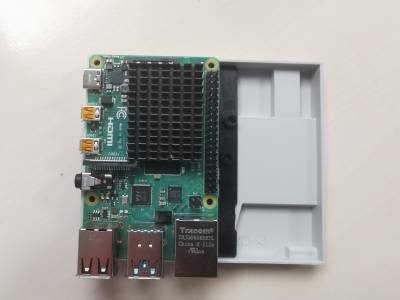
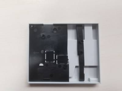
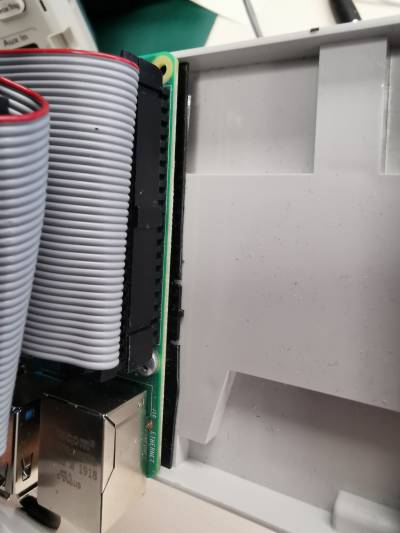
- Attach the Raspberry Pi to the plate with the included screws
- Remove the plastic coating from the sticky adhesive in the case and use this to affix the Pi into the left side of the case
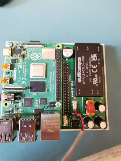
- Trim the through hole components on the PSU assembly and apply double sided adhesive tape, affix to the right side of the case
- Solder the wire to the solder points as pictured


10902-A Build Instructions
Cut the Ribbon cable to required width and then cut the length to 90mm see pic below. Attach the connector and slide into position, see pic below
Crimp both ends into place, see pics below
- Connect the ribbon cable and attach the heatshield using it's sticky pad
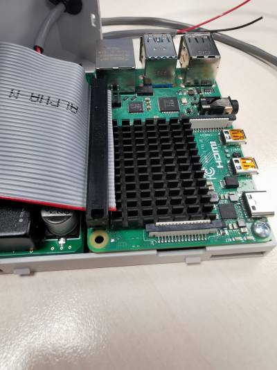

Ensure ribbon cable is not folded over the heatsink, it must fold over the black PSU
Cut cable (200584) to 1M (1000mm) and strip both ends.
- Put the grommet into the hole on the case and feed the wire through
- Use a cable tie on the wire on the inside of the case as pictured
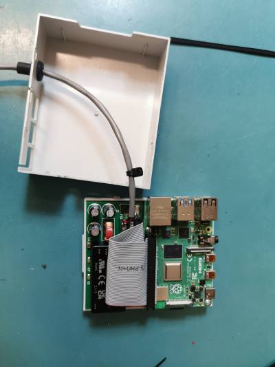
- Attach the top half of the case and pull through the slack on the cable, so that the cable tie prevents the cable being pulled any more.
- Insert the SD card
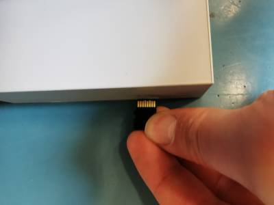
- Affix the label


Programming Instructions
- Open Balena Etcher
- Load the image file from S:/Code/Production/6010 Ethernet Adaptor
- Insert the SD card into the SD card reader
- Follow the instructions on screen to program the card
Testing Instructions
- Connect the ethernet cable
- Connect the HDMI cable to the test bench touch screen
- Connect the USB cable from the test bench touch screen
- Connect the power and apply 24V
- Turn on, after 20 seconds Poseidon will have loaded
- Ensure that the touch screen responds to touch, see pics below.


Packaging
Place warranty label over SD card slot.

coil cable loosely and place cable ties in position, place in a large bubble bag. use RPT 103 box with sleeve, see pics below.
internal/proddocs/6010.1659608872.txt.gz · Last modified: 2023/07/12 14:11 (external edit)