
This is an old revision of the document!
Warning: Undefined array key 1 in /data/docs.osukl.com/public_html/lib/plugins/note/syntax.php on line 103
Warning: Undefined array key 1 in /data/docs.osukl.com/public_html/lib/plugins/note/syntax.php on line 103
Warning: Undefined array key 1 in /data/docs.osukl.com/public_html/lib/plugins/note/syntax.php on line 103
Warning: Undefined array key 1 in /data/docs.osukl.com/public_html/lib/plugins/note/syntax.php on line 103
Warning: Undefined array key 1 in /data/docs.osukl.com/public_html/lib/plugins/note/syntax.php on line 103
Table of Contents
5250 Build Instructions
Atmel Programming
The PCB requires both bootloader via Atmel Studio and main program via Atmel FLIP. Before continuing connect the PCB to the NMEA cable at your bench and power on the device to 12V.
Bootloader
Connect the Atmel ICE tool to the PCB.
- Open Atmel Studio
- Go to Device Programming
- Set fuses as per below picture
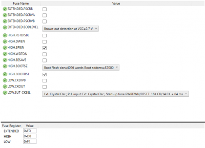
- Flash the AVRBootloader.hex file from S:/Code/Production/5250 Deck Gauge/AVRBootloader.hex
- Display should now read '88'.

Main Program
- Power off the PSU
- Hold a magnet over the right lip of the 7 segment display
- Power on the PSU. Display should read '8'. If it does not, repeat steps 1-3.
- Open Atmel Flip
- Ensure ATMega64C1 is the selected device
- Select Setting>Communication>CAN>PEAK>250kbit/s Then press Init and Connect (repeat this step up to 5 time until device is connected)
- Load the latest 5250 named hex file from S:/Code/Production/5250 Deck Gauge/
- Press Run
Hardware Assembly

Rest printed glass (202271) onto the gasket, making sure correct orientation of glass and bezel casting. One hole at top and two holes at bottom.

Degrease polyacetal body with IPA and allow to dry before fitting. Place black polyacetal body into bezel casting and use hand press to snap into place.
Warning
BE SURE BLACK BODY IS COMPLETELY FITTED TO THE BEZEL WITH NO ANY GAPS. APPLY HAND PRESS DEVICE FROM DIFFERENT EDGES TO ENSURE BLACK BODY INTO PLACE.

Use hand press to snap black body into place, make sure to protect the body from damage. See next image.

Protect black plastic body.
Remove rubber grommet from connector.

Warning
BEFORE START MIXING THE CLEAR POTTING, CLEAR THE PRINTED GLASSES WITH IPA AND COTTON BUD.
Pour clear gel (WACKER SILGEL) first - with mixing ratio 1.5/1 (Compaund A/B), weigh into cup and then follow document Epoxy degassing instructions QMF18 on how to degas the epoxy. Check all air bubbles have dispersed.
Mixing Table Compaund A - Compaund B
- 1.5gr - 1gr
- 10gr - 6.6gr
- 15gr - 10gr
- 20gr - 13.33gr
- 25gr - 16.66gr
- 30gr - 20gr
- 35gr - 23.33gr
- 40gr - 26.66gr
Note
MIX CLEAR POTTING FOR 60 SECONDS

Following Clear epoxy procedures 201266
Warning
ADD JUST ENUGH TO COVER THE PRINTED GLASS A THIN LAYER. NEVER OVERFILL CLEAR POTTING.

Brush face of display with degassed epoxy, and then gently place PCB into the clear epoxy taking care to align PCB in the correct orientation. Ensure PCB display lines up with printed window.


When clear epoxy is dry and PCB is securely in place, fill back of Deck Gauge with black epoxy compound 201265. Fill just below the lip of rotary switch taking care not to let potting compound go down into connectors or switch. Leave to cure for 24 hrs.
This board is now potted in black resin 201265 up to the level of the rotary switch.

connect assembly to Monex set serial numbers and double check the function of the display.

Warning
Before packing print Manual and label unit.
Return the hex nut to connector, AND COVER WITH BLUE FILM.


